Code Lock
Background Info
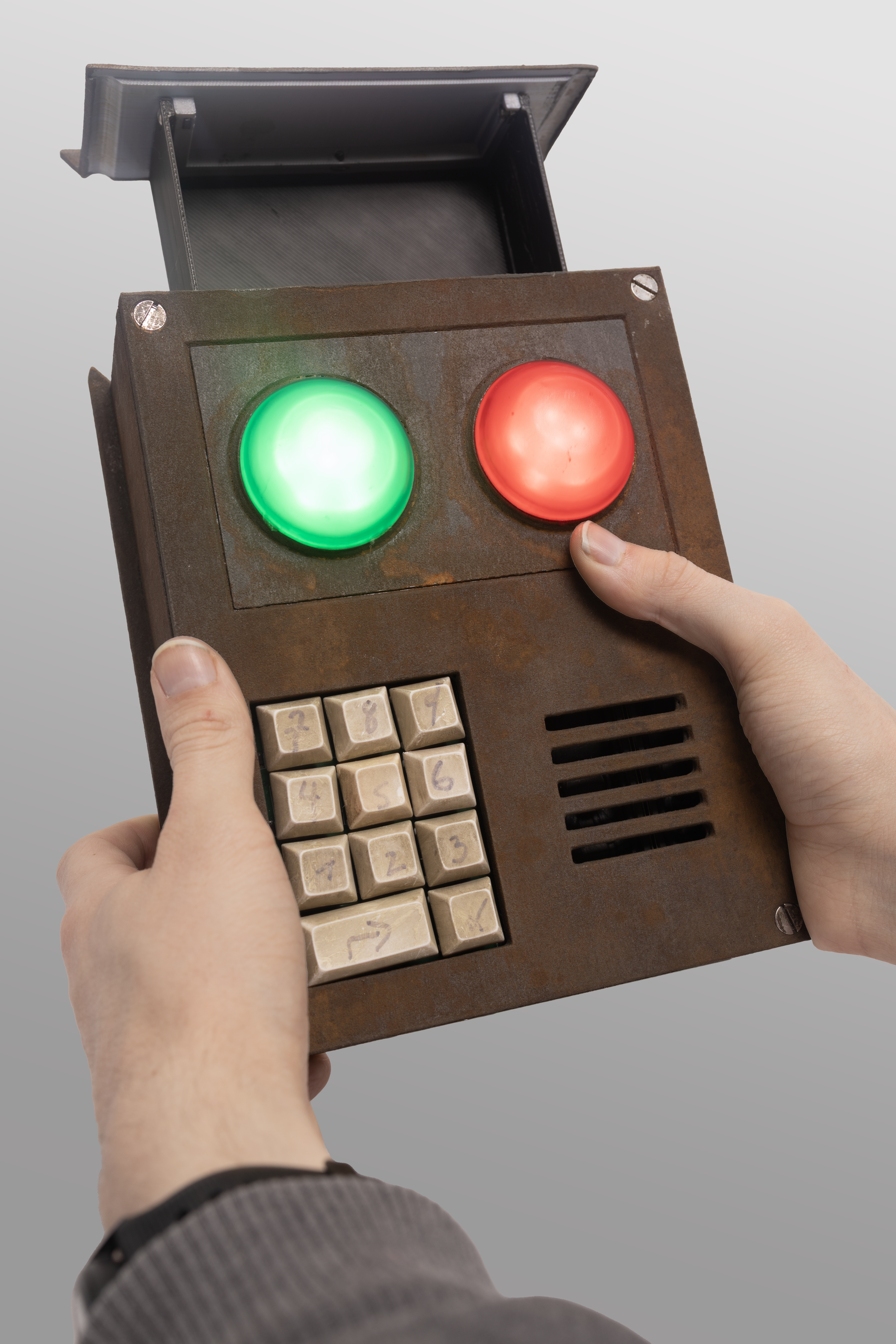
What is the code lock?

The code lock is from the game Rust a multiplayer survival game where players need to gather resources, craft weapons and build bases to survive. The code lock is an item that can be used to lock doors or chests to keep other players from accessing them.
Project Overview
Design Goals
When first coming up with the design for the lock there were a few features I knew needed to be included if I wanted it to feel like the actual code lock from the game.
- A red and green working light for indicating whether the correct or incorrect code was entered
- Audio feedback with speakers for each button press
- A full size keypad with real keys
- A real rusted outer body

Initial Concept: A Real Door Lock
When I first decided to build the code lock, I was considering making it into a real door lock as this would be its most obvious function. I even went as far as purchasing electromagnets for the locking mechanism. But after thinking over it more I realized that this would not be practical for a few reasons:
- Battery charging would be difficult
- Installation would require custom fitting for each door
- Weather resistance would be necessary for exterior doors

Changing The Design
With the door locking function scrapped, I needed to develop alternative “real” functionality beyond just replicating the lights and sounds from the game.
After exploring several options, I settled on integrating a hidden storage compartment that is revealed when the correct code is entered.
Storage Compartment
The new functionality required solving three different problems:
- Designing a smooth sliding mechanism for the box
- Implementing an electronic locking system
- Creating a spring-loaded mechanism for automatic opening

Storage Compartment Evolution
In my first prototype I had the storage compartment only in the front half of the code lock body. This design severely limited the usable space and made accessing items difficult.
In the second iteration, I extended the compartment to span the entire length of the code lock. This modification increased the storage length by 2x and made it much easier to access items.

Electronic Lock
Luckily creating the locking mechanism was a lot easier than I expected. I found an off the shelf solenoid lock that fit perfectly inside the code lock. It required no power to stay locked and a one second 5v pulse to unlock.

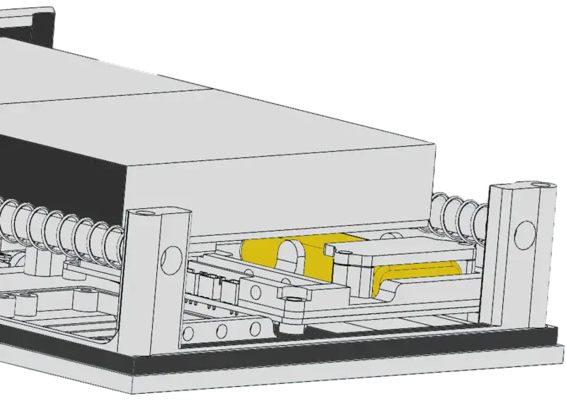
Sliding Mechanism
With the locking mechanism solved, the storage compartment still needed a way to slide open and closed smoothly. For this, I decided on using two 8mm diameter rods flanking the storage box that served as guides. The box itself had 8mm drylin bearings attached to it that slid along these rods.
To push the box open when unlocked, I added springs on either side that fit over the rods, resulting in the box being automatically pushed out when the lock was released.

LED Development
Visually one of the most important features of the code lock are the red and green LEDs. They are approximately 20mm in diameter and 10mm in height, so no off-the-shelf LEDs would be nearly large enough to be used.
I decided to use a cluster of 6 programmable LEDs as the light source. Specifically, I used the WS2812B LEDs that allow for complete customization of the color and for fading/flashing effects.

LED Diffuser Development:
- First Attempt: 3D printing with clear polycarbonate
- Result: Extremely visible layer lines created an uneven light distribution, looking nothing like the smooth in game light

- Second Approach: Silicone casting
- Created a “master” part from polished resin print
- Made a silicone mold from the master
- Cast parts using clear resin with red and green tint
- Result: Bubbles and imperfections were very obvious when lit

- Improved Casting: Pressure chamber curing
- Used pressure chamber to eliminate bubbles
- Added silicone to the inner section for better diffusion
- Result: Perfect, evenly spread light throughout the piece

Main Circuit Design
The next challenge was making the actual circuit board. Luckily I knew what features I wanted to include:
- 11 key matrix keypad
- Speaker for audio feedback
- 5V input to power the code lock
- 3.3V to power the microcontroller
- Microcontroller
With all of the features I wanted to include decided, I started making the first circuit boards.
Parts Used:
- ESP32-S3 - Microcontroller
- 2X - MAX98357A - Audio Amps
- SD Card
- MT3608 - 5V - Buck Boost
- HT7333 - 3.3V - LDO
- 11 Key Matrix Keypad

Input Power
Initial Power Approach
With the first circuit board design, I did not put much thought into power and simply used a USB-C cable for 5V, planning to have the code lock always connected to an external power source.
Transitioning to Battery Power
After thinking about it more, I realized that a battery-powered design would be more practical. This required adding a completely new section to the circuit board.
Battery Selection
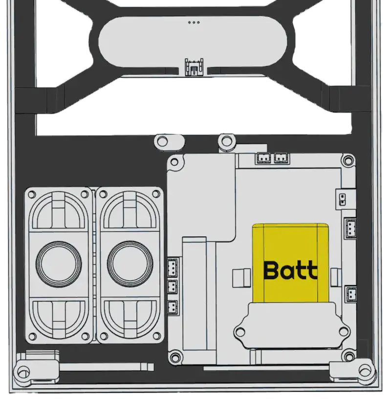
For the battery itself, I selected a 2000mAh lithium polymer pouch cell :
- Highest capacity that would fit within the available space
- Relatively thin profile allowed the compartment to slide over top of it
- lots of charge controllers available for single cell lithium batteries
Charging Circuit
For the charging circuit, I implemented the following components:
Charging IC:
- Selected the TP4056, a common single-cell lithium battery charging IC
- Includes overcharge protection features
Power Path Management:
- Added a battery disconnect feature during charging
- This was necessary because the TP4056 won’t charge correctly if the battery is simultaneously powering the circuit
- Implemented using a simple MOSFET-based power path management circuit

Enhanced Charging Feedback
As a bonus feature, I connected the charging status LEDs from the TP4056 directly to GPIO pins on the ESP32-S3. This allowed me to:
- Monitor charging status in software
- Create custom charging animations on the main code lock LEDs
- Provide visual feedback when the battery is fully charged

Wireless Charging
With the code lock being battery-powered, I needed an elegant way to recharge it without compromising the aesthetic.
Choosing a Charging Method
My initial thought was to include a USB-C port, which would have been easy to implement but would have detracted from the look of the final code lock. I decided instead to implement wireless charging removing the need for a USB-C port.
Implementation
Receiver Design:
- Found an off-the-shelf coil + charge circuit that output 5V
- Connected this to the input circuit of the code lock
- Mounted the coil to the back wall of the code lock

Charger Base:
- Selected a generic Anker 10W wireless charger as the power source
- Created a custom 3D-printed housing designed to look like a display stand
- Integrated the charger into the base

Alignment System:
- Added a series of magnets in both the charger and code lock
- This ensured proper alignment for optimal power transfer
Solving the Weight Problem
After printing and assembling the stand, I quickly discovered it was too light. The magnets in the code lock would actually lift the entire base when picking it up.
I considered several weighting options:
- Sand (messy, difficult to contain)
- Concrete (messy, difficult to contain)
- Metal weights (expensive, difficult to source)
The solution I found was to use pennies:
- Inexpensive and readily available
- Easy to add to the hollow base
- Dense enough to provide significant weight
- Simple to secure in place


Power Optimization
Because the code lock is battery powered the amount of power draw is important to keep as low as possible.
Initial Power Consumption
In standard operation, the code lock consumed between 60-70mA, with even higher peaks when unlocking or activating lights. At this rate, the 2000mAh battery would be fully drained in about a day.
Power Optimization Strategy
I implemented several optimizations to extend battery life:
1. Microcontroller Sleep Mode
- Put the ESP32-S3 into light sleep mode after 10 seconds of inactivity
- Reduced passive power draw to 15mA
2. LED Power Management
- Discovered that the WS2812B LEDs drew 3mA even when displaying no light (in their “off” state)
- Added a MOSFET with its gate connected to a GPIO pin to completely disconnect power when not in use
- Further reduced power draw by 3mA when LEDs weren’t needed

3. SD Card Power Control
- Surprisingly, the SD card was a major power consumer at 7mA even when idle
- Implemented another MOSFET to disconnect power after loading sounds into memory
- Saved an additional 7mA

4. Additional Optimizations
- Replaced 10kΩ pull-down resistors with 100kΩ alternatives
- Various other small circuit optimizations
Final Results
These combined changes reduced the passive power draw to just 2.5-3mA - a 95% reduction from the original design.

Metal Paint
Creating a convincing metal finish was crucial for the code lock’s final look. My first thought was to use a metalic spray paint. But after some testing I found that it looked artificial and fake.
Developing Custom Metal Paint
I ultimately decided to create my own “metal paint”:
Materials Used:
- Sourced two grades of metal powder (fine and coarse)
- Selected clear acrylic paint as the binding medium
- The acrylic paint worked to suspend the metal particles and bond them to the printed surface
Formulation Process:
- Experimented with different metal powder-to-paint ratios
- Tested various application techniques and layer counts
- Refined the formula through multiple iterations

Testing and Refinement
Achieving the right metal appearance required lots of trial and error:
- Too little metal powder resulted in an unconvincing finish
- Too much powder created adhesion problems
- Layer thickness significantly affected the final appearance


Failed Formula
Here is an example of a failed formula that caused the metal paint to clump up.

Successful Formula
The final formula created a surface that:
Had smooth metal texture
Would react with rusting agents
Maintained good adhesion to the printed parts
Final Formula:
4 parts iron100
4 parts clear acrylic paint
1 part micronized iron powder

Rust Application Process
With the paint working well, I still needed to actually apply rust.
Initial Rust Attempts
At first, I thought this would be as simple as applying salt water with a spray bottle. But surprisingly, this had minimal effect on the metal surface.
Developing the Rust Formula
After some research, I created a more effective rusting solution:
Basic Rust Mix:
- 16.6 parts of water
- 2 parts of salt
- 1 part of 12% hydrogen peroxide
- 0.4 parts of 80% vinegar

This solution immediately produced heavy rusting when applied to the metal-painted surfaces.
Overcoming Challenges
However, I soon encountered the opposite problem - too much rust. After a few hours, the parts developed a uniform brown color that no longer looked like authentic rust.

Refining the Process
To achieve a more realistic rust appearance:
- Apply Less Rusting Solution: I made sure not to let the rusting solution pool on the surface.
- Color Variation: I wanted to some how incorporate yellow rust tones alongside the brown
Experimenting with Copper Sulfate
After some research I discovered copper sulfate, which has the ability to create bright yellow rust on iron surfaces.
I tested over 10 different combinations of salt, vinegar, copper sulfate, and hydrogen peroxide. Surprisingly, all these combinations produced worse results than my original solution. Something about the copper sulfate mixed with the other chemicals created solutions that no longer rusted the metal.

Final Two-Step Process
The solution came in separating the applications:
- Apply the original rusting mix with very light coats
- After partial drying, spray on a copper sulfate solution:
- 3 parts of water
- 0.6 parts of copper sulfate

This two-step approach produced the perfect mix of brown, red, orange, and yellow rust tones I was after, creating an authentic rusted look.


Keycap Weathering
The final piece for the code lock was creating the weathered keycaps. I started with standard white mechanical keyboard keycaps as the base.

Replicating the In Game Look
Looking at the in game code lock, the numbers look like they are hand drawn with a marker. To match this style:
- I used a black Sharpie to draw numbers on each key, mimicking the imperfect handwriting from the game
- This created the basic numbered appearance, but the keys still looked too new and clean

Creating the Aged Appearance
To achieve the worn, discolored look of old plastic:
- Yellowing Effect:
- Applied a yellowish acrylic paint wash
- Heavily coated each key, then immediately wiped most off
- This left behind a subtle yellowed tint typical of aged plastic

- Dirt and Grime Simulation:
- Used a green/brown paint mixture for the final weathering
- Applied heavily then quickly wiped most away
- This left the keys looking well used and dirty


Final Result


Bill of Materials (BOM)
Electronics
| Component | Quantity | Notes |
|---|---|---|
| Main PCB | 1 | Custom designed |
| LED PCB | 1 | Custom designed |
| 3W Speaker | 2 | |
| Electronic Lock | 1 | 5V solenoid type |
Input Components
| Component | Quantity | Notes |
|---|---|---|
| 1U Keycap | 10 | Standard mechanical keyboard keycaps |
| 2U Keycap | 1 | For enter key |
Motion Components
| Component | Quantity | Notes |
|---|---|---|
| 8mm Linear Rod (200mm) | 2 | For sliding mechanism |
| 8mm Drylin Bearing | 2 | Self-lubricating linear bearing |
| Spring (200mm) | 2 | 11mm ID, 0.6mm diameter |
| Spring (15mm) | 2 | 11mm ID, 0.6mm diameter |
Charging Components
| Component | Quantity | Notes |
|---|---|---|
| Wireless Charging Circuit | 1 | Receiver module |
| Anker Wireless Charger | 1 | 10W charging base |
Fasteners
| Component | Quantity | Notes |
|---|---|---|
| M5 60mm Flat Head Screw | 4 | Main body assembly |
| M5 Heat Insert (7-8mm) | 4 | Main body assembly |
| M4 20mm Cap Head Screw | 2 | Lock mounting |
| M3 6mm Button Head Screw | 2 | Lock mounting |
| M3 Heat Insert (4-5mm) | 2 | Lock mounting |
| M3 Square Nut | 3 | Drawer assembly |
| M3 6mm Counter Sunk Screw | 3 | Drawer assembly |
| M3 8mm Self Tapping Screw | 14 | Internal assembly |
Chemicals
| Component | Quantity | Notes |
|---|---|---|
| Salt | 1 | Rusting solution |
| Hydrogen Peroxide | 1 | Rusting solution |
| Vinegar | 1 | Rusting solution |
| Copper Sulfate | 1 | Rusting solution |
Paints
| Component | Quantity | Notes |
|---|---|---|
| Yellowish Acrylic Paint | 1 | Keycap weathering |
| Green/Brown Paint | 1 | Keycap weathering |
| Clear Acrylic Paint | 1 | Metal paint |
| Iron100 | 1 | Metal paint |
| Micronized Iron Powder | 1 | Metal paint |