Ghost
Early Design Goals
When I first decided to build the Ghost, I had three main design goals in mind:
Easy Customization of the Outer Shell: I wanted the outer shell of the Ghost to be easily customizable. This meant designing it in such a way that different parts could be swapped out or modified without much hassle. The idea was to allow for various aesthetic changes and upgrades, making it possible to personalize the Ghost.
Rotation of the Back Half of the Ghost: Another key goal was to enable the back half of the Ghost to rotate, mimicking the in game Ghost. Getting this to work was a challenge as I had to figure out how to connect the two halves together while still allowing for rotation.
Motion in the Front Eye: The final design goal was to incorporate motion in the front eye of the Ghost. Using a screen with a high enough frame rate this would add a lifelike element to the ghost. The challenge was mimicking the animations in game and making the motion random.
Early Failures
Testing Size and Space Limits
In my initial attempt, I underestimated the importance of space constraints and decided to use discrete circuits for each function. After printing each piece and soldering everything together, it became very clear that the components would not fit within the available space.
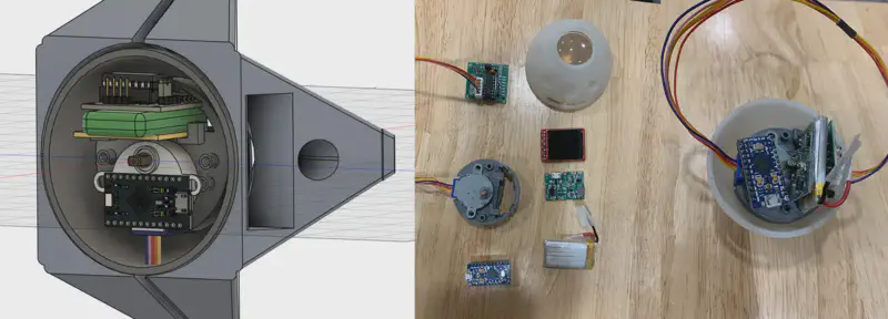

This realization led me to the create the next version of the Ghost. By designing a custom circuit board and removing the battery, I was able to significantly reduce the space constraints. However, this new approach introduced a new set of challenges that needed to be addressed.
Testing Electronics
I started by experimenting with a premade Adafruit board to test displaying GIFs, since I had never designed a circuit board before.
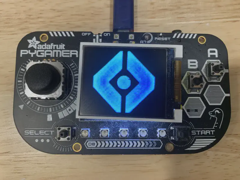
Attempting My Own Circuit Design
This initial test worked well, so I tried making my own circuit based on the Adafruit board. However, without much experience in circuit design and programming, very few parts of my board actually worked.
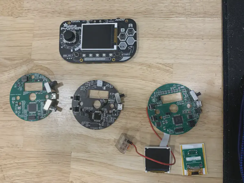
Learning from Failures
After troubleshooting issues for a while and making little progress, I decided to pause work on the Ghost and focus on other smaller projects. During this time, I gained much more knowledge about PCB design, programming embedded devices, and improved my soldering skills. This learning phase was crucial for actually having a chance of succeeding with the Ghost.
Building a Phoenix Kit
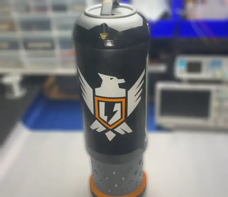
One of the projects I worked on during this time was building a phoenix kit from the game Apex Legends.
Prototyping Version Two
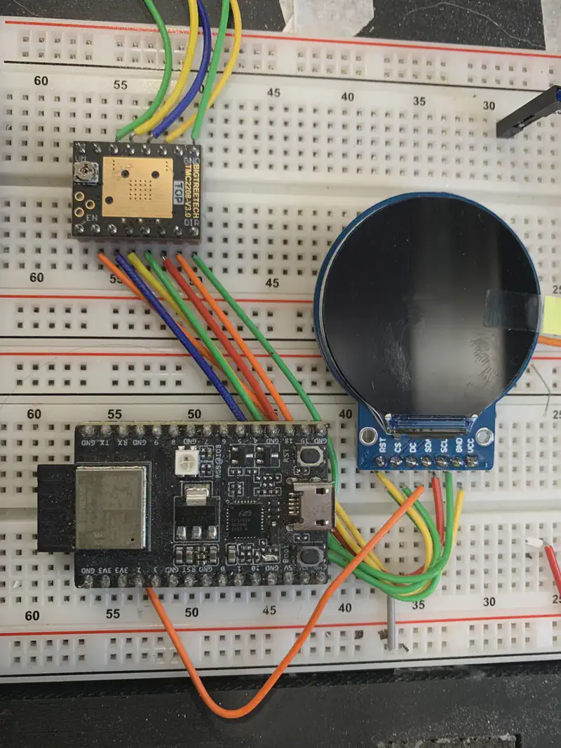
For the next iteration of the Ghost, I decided it was best to start from scratch. I had learned enough to realize that trying to fix my previous build would be a waste of time. With a much better understanding of prototyping and more hardware to experiment with, the first step was to lay everything out on a breadboard.
Breadboard Prototyping
Instead of designing the circuit right away as I did previously, I used a breadboard to prototype the design. This approach allowed me to quickly identify and fix any obvious wiring issues before committing to a final circuit design.
Designing the PCB
Once I had the hardware working and a basic program running, I moved on to designing the PCB.
- Circuit Design First: Unlike my previous attempt, I focused on designing the circuit first. This approach ensured that all components fit together and worked correctly before moving on to the physical design of the shell.
- 3D Modeling: After finalizing the circuit design, I created a 3D model of the shell around it. This method helped avoid the problems I encountered before, where I had to adjust the circuit to fit a pre-made shell.
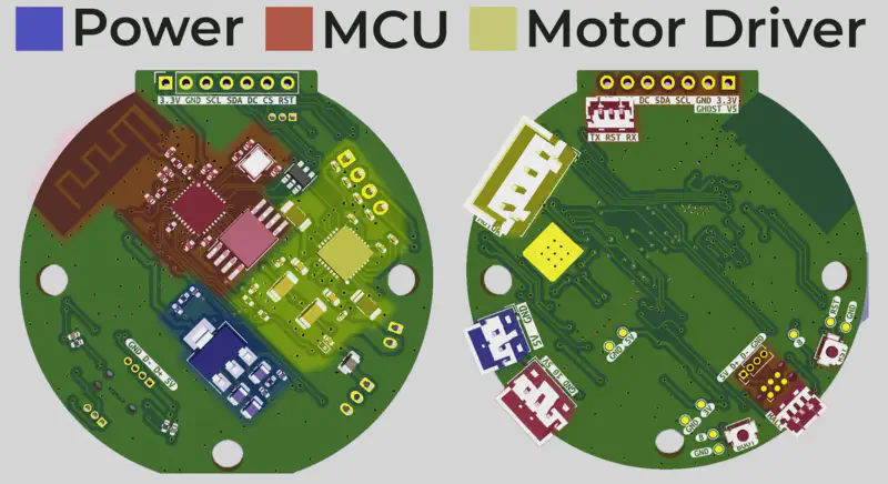
Some of the major changes in the new design include:
- Microcontroller: Switching from an Atmel microcontroller to an Espressif microcontroller.
- Display: Upgrading to a larger round display instead of the previous square one, making integration into the ghost shell easier.
- Display Mounting: Mounting the display directly onto the PCB, which simplifies the design and reduces the overall size.
- Power Source: Eliminating the use of a battery, which reduces the complexity and space requirements.
- Motor Driver: Integrating a motor driver IC directly onto the PCB, saving space and simplifying the design.
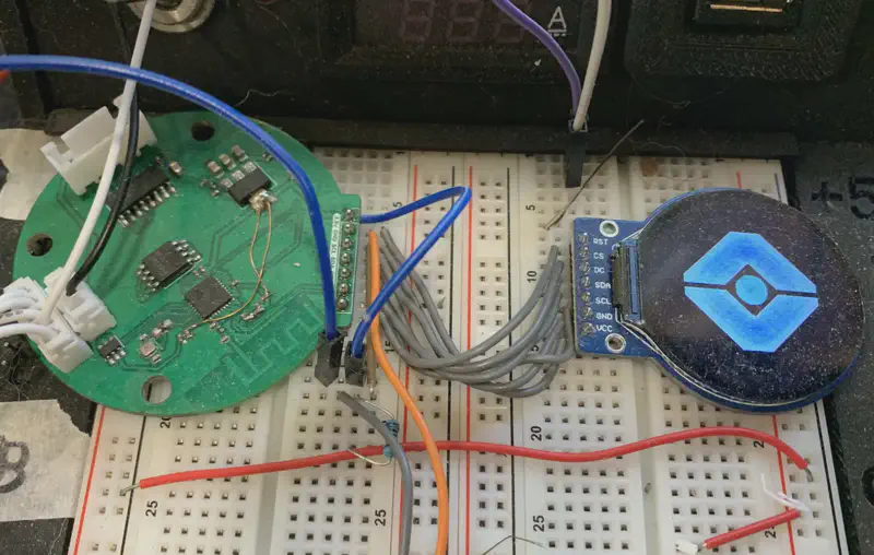
This new PCB design ultimately became the final overall design, with only minor adjustments needed when other components had to be changed.
In addition to the new PCB, I also needed to design a new body for the Ghost to accommodate the updated components and layout.
3D Modeling Internal Shell
Top Shell
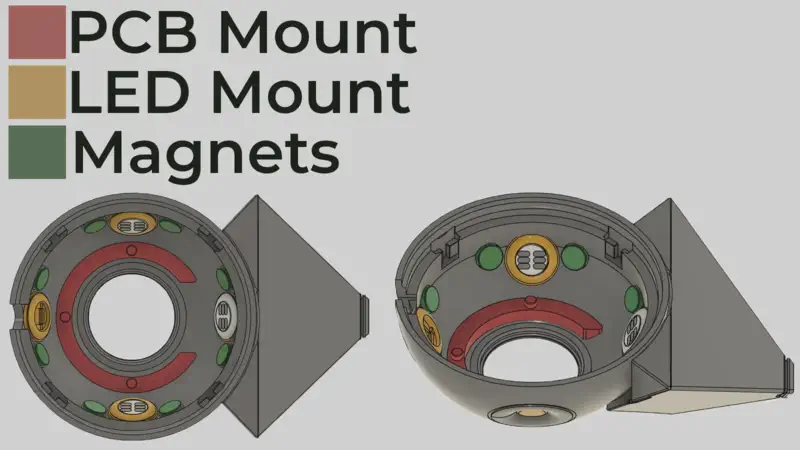
Before designing the main shell, I needed to determine all the internal hardware requirements and the features that would interact with the shell. This included considerations for mounting external pieces and how power and data would be fed into the Ghost.
The internal hardware components included:
- 4 WS2812b LED modules
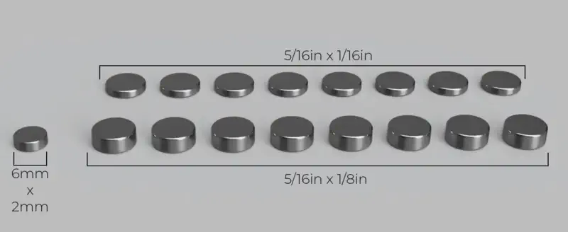
- 16 magnets for mounting external shells
- Main PCB and display module
- Motor
- Lens
- 8mm OD hollow metal rod with internal power/data cables
Bottom Shell
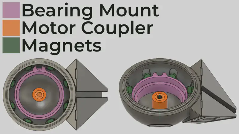
The bottom half of the shell is the rotating portion. Due to its rotation, no electronics can be placed here as wires passing from one side to the other would get tangled. The only solution to this would be using a slip ring, which I decided against. Therefore, the bottom shell only includes the following features:
- Magnets for connecting to the external shell
- A central post that directly connects to the motor
- An outer bearing to take the load off the motor
3D Modeling External Shell
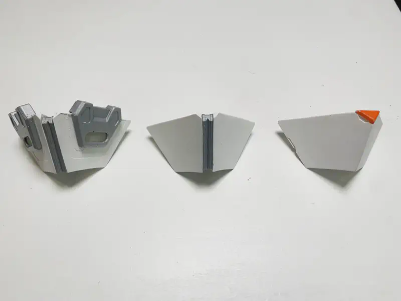
To maximize customization potential, I decided to split the shell into four identical pieces per side, totaling eight pieces for the entire ghost. This modular approach allows for easy interchangeability and design variations. So far, I have designed three unique types of shell pieces.
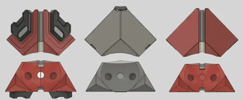
Each type of shell piece is functionally identical, with the only differences being cosmetic. The only exception is a special shell piece needed for the front bottom position, which has a cut-out section to accommodate the central metal post that connects to the stationary front half of the ghost.
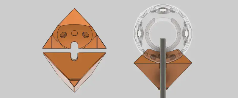
Modular Design Pieces
In the center of the two red shells shown below, there is a separate piece that slots into place, allowing for even more customization.

Additionally, the black piece shown below is another design element that slots into place over the light guide. It uses a magnet to stay in place, making it simple to add new pieces in the same location in the future.
Light Guide
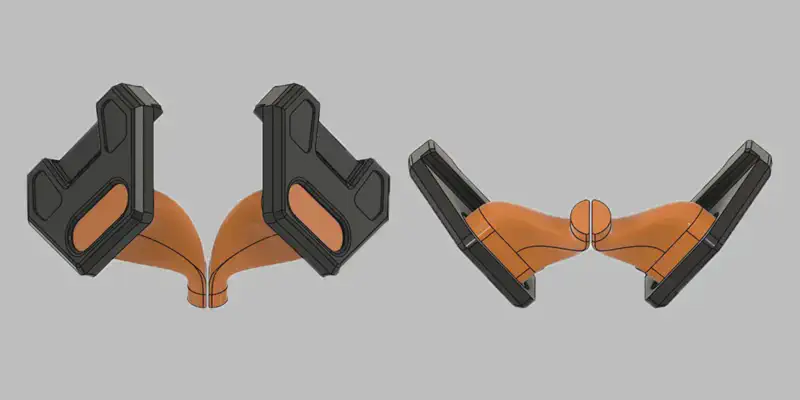
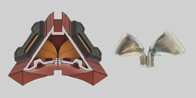
The light guide, highlighted in orange, is a clear component that starts at the bottom of the shell, works its way through the center, and emerges from the shell at the ends. This piece channels light from the LEDs in the central sphere of the Ghost shell to the outside, making the light visible.
Below, on the left, is a cutaway view of the hollow shell, and on the right is a finished light guide.
Motion
Initial Motor Tests
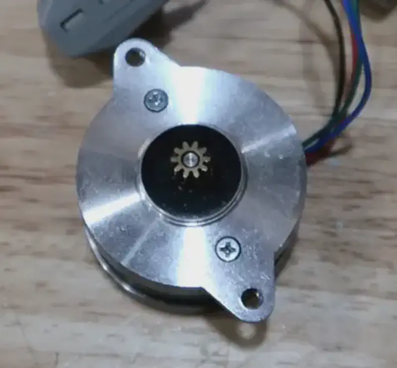
During the initial motion tests, I used the 28BYJ-48 stepper motor due to its small size and low cost. However, when testing the motor under load, it became clear that it lacked the necessary torque to spin the shell reliably. To fix this issue, I needed to find a new motor and motor driver. Ultimately, I chose the 36mm Nema 14 pancake stepper motor paired with a TMC-2208 stepper motor driver. This combination provided the high speeds I wanted while still fitting within the small footprint of the ghost shell.
36mm NEMA 14 Pancake Stepper Motor Specifications
- Type: Bipolar Stepper Motor
- Operating Voltage: Typically 6.5V - 12V
- Step Angle: 1.8° (200 steps per revolution)
- Torque: 80 - 100 mN.m
- Current Consumption: Typically 0.5 - 1A per phase
- Dimensions: 36 mm diameter
Mounting the Motor
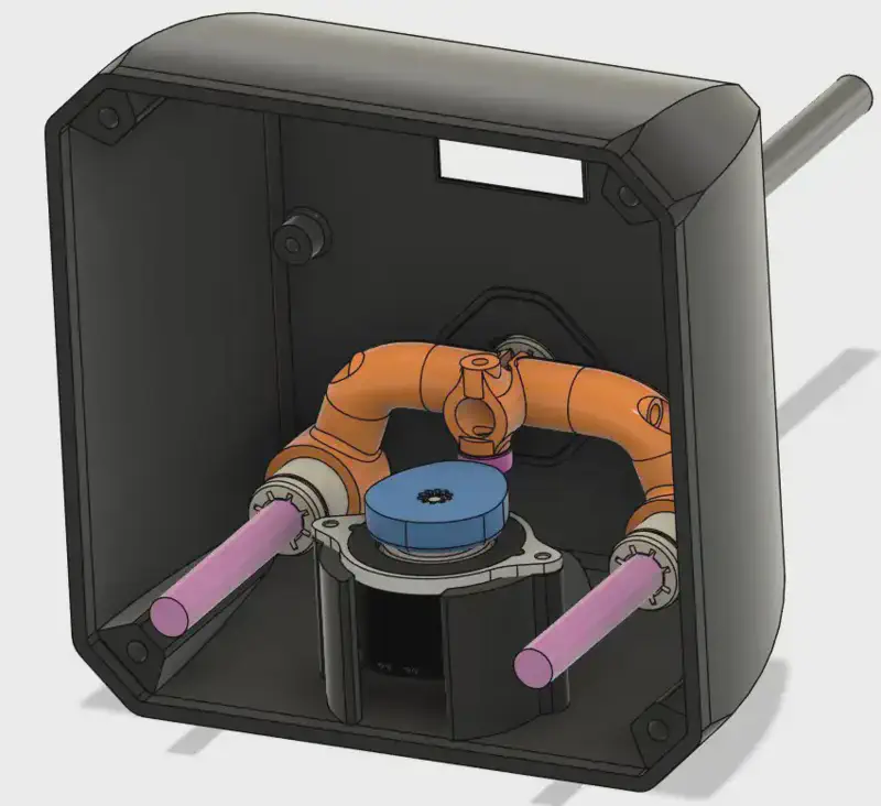
One significant challenge was accurately mounting the motor inside the shell. The main body of the shell is made of polyurethane, which is not suitable for directly threading screws or installing heat-set inserts. This material limitation meant that I couldn’t directly attach the motor to the shell.
To fix this, I designed secondary components made of PLA (or any thermoplastic). These pieces interface with the main polyurethane shell and provide the necessary structure to install heat-set inserts that the motor mount threads into.
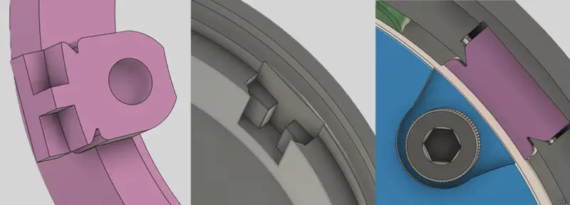
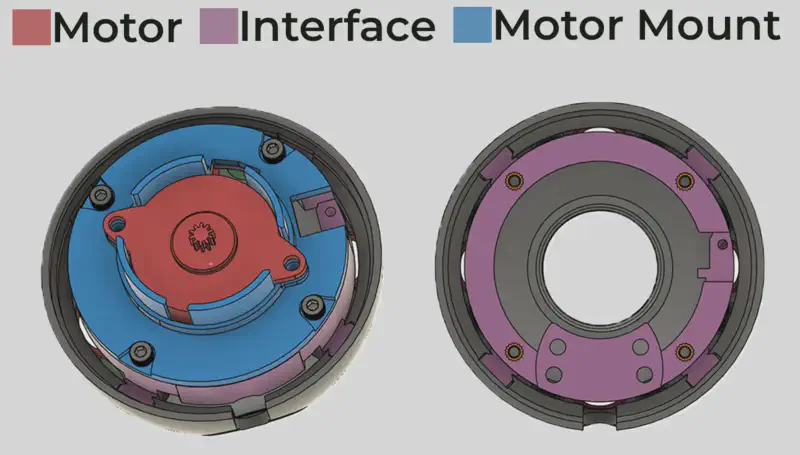
Once fully assembled, this setup allowed the front half of the shell to interface with the rotating back half. The only piece missing was a bearing to provide a secure connection between the two sides and to take the weight off the motor itself.
Adding a Base
With the Ghost itself finished, it needs a base to hold it upright. While a simple plastic stand could work, the additional space allows for incorporating several more features.
User Menu
The primary feature I wanted to add is user controls, enabling easy customization of various features in the ghost such as LED color, rotation speed, eye color, LED animations, and more.
For user input, I chose a 1.3-inch OLED display, a rotary encoder, and a push button.
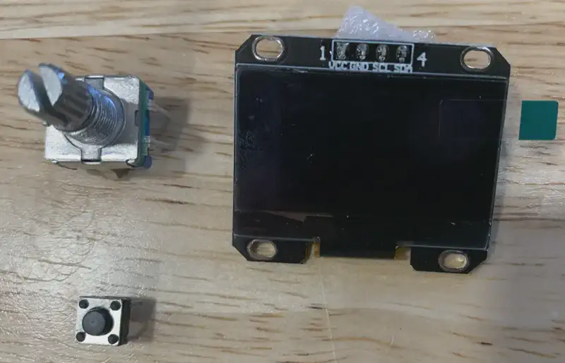
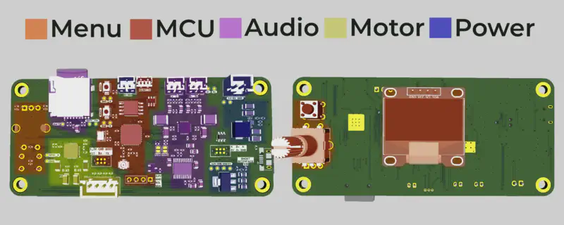
To implement these controls, a second circuit board is required in the base. This board will take user inputs and translate them using a microcontroller into serial commands. These commands, along with power, will be sent to the main board in the ghost.
Hover Effect
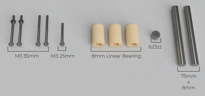
One of the most difficult effects I wanted to add was making the entire ghost appear as if it is hovering. Fortunately, I could again use a 36mm Nema 14 stepper motor and TMC-2208 driver for this purpose. The main challenge was efficiently translating the rotational motion into linear motion within a small footprint.
Initial Design: Piston Mechanism
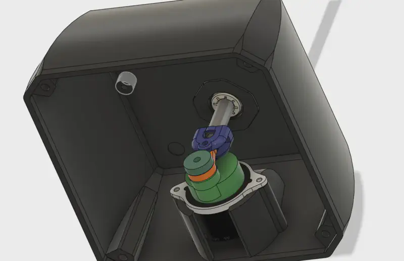
In my first attempt, I designed a piston-like mechanism that pushed against a central rod riding in a linear bearing. While this design worked, it had several flaws. The primary issue was the presence of too many small parts, each introducing some play that led to unstable and wobbly motion. To address this, I added a small metal rod riding in a groove to limit unwanted motion. Although this solution worked to some extent, it was always either too restrictive causing the motion to bind, or too loose, resulting in wobbly motion.
Improved Design: Cam Mechanism
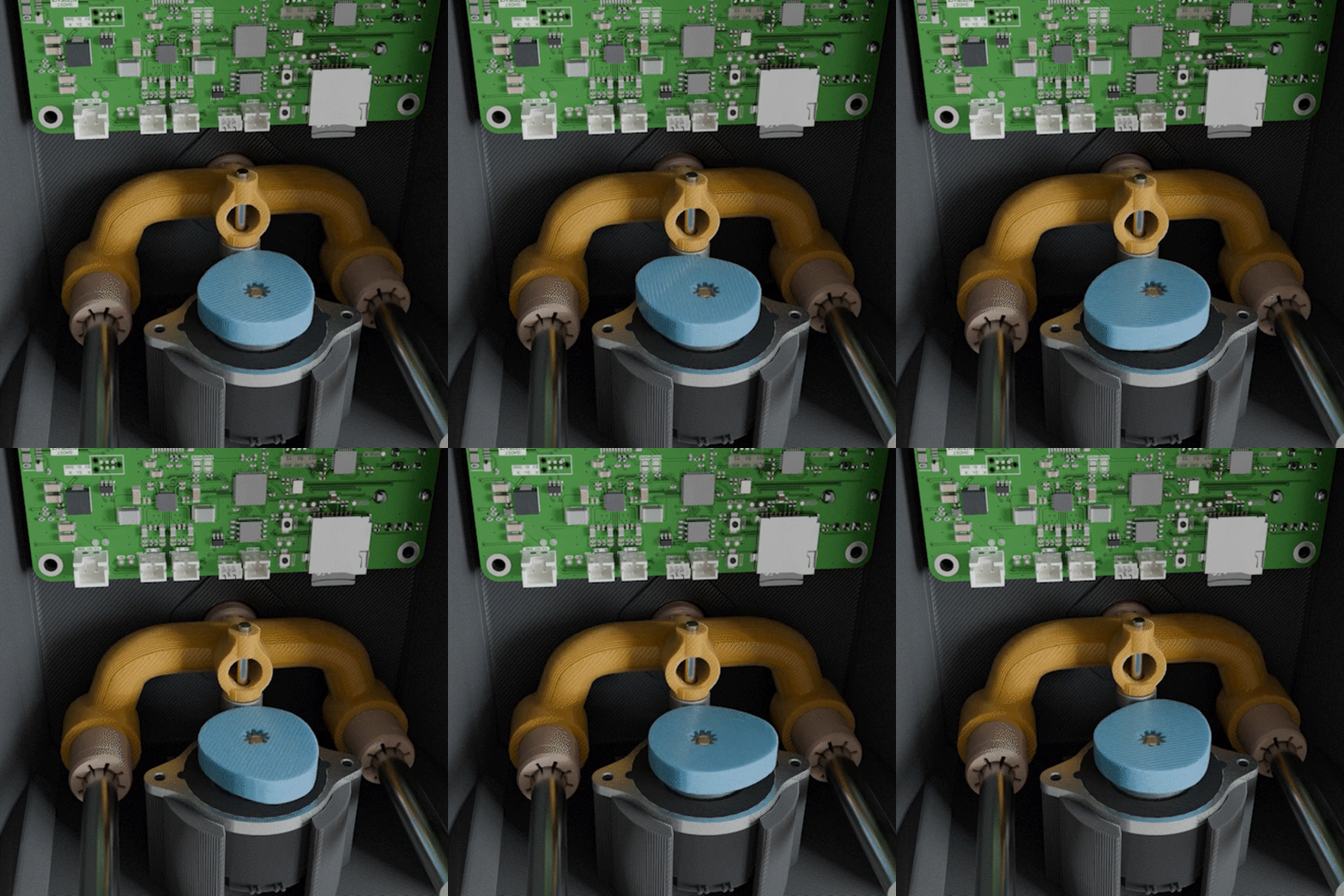
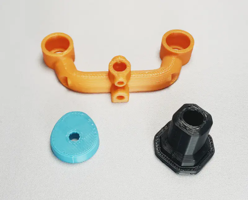
In my redesign, I prioritized stability, smooth motion, and a low part count. Instead of piston based motion, I opted for a cam mechanism. In this design, the cam is the only component attached to the motor, pushing on a small bearing connected to the central rod. To stabilize the rest of the assembly, I added two extra linear bearings and linear rods. This setup was much more stable and consistent than the previous design.
Fixed Base
Even with the improved cam design, there were still issues with the motion stability. Because of this I decided to make a second version of the base that doesnt Include the hover effect. The stand is instead rigidly connected to the base. I plan on continuing to work on the hover effect in the future but for now this is the version I plan on actually making.
Voice
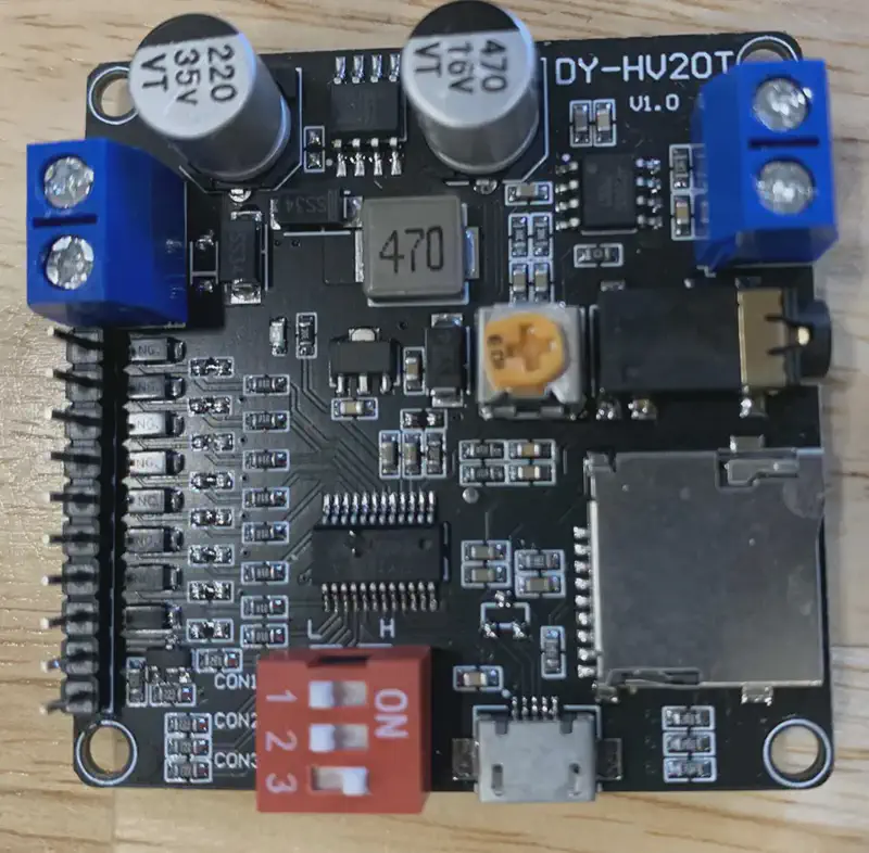
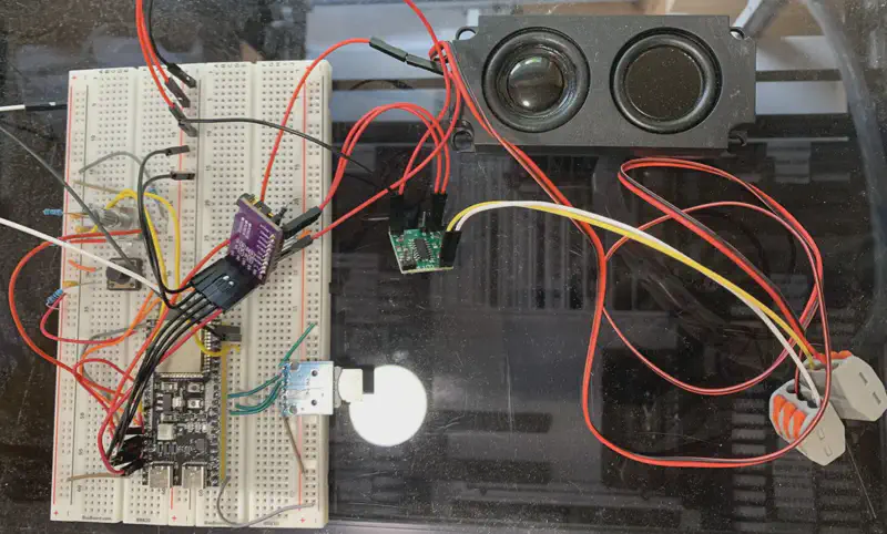
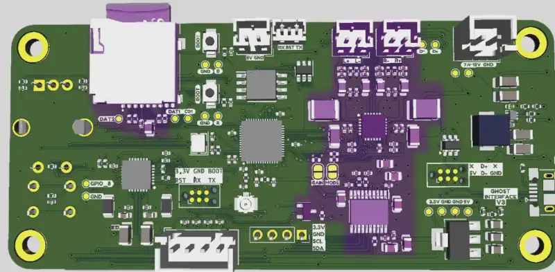
After verifying that everything worked, I added the audio section to the existing board.
3D Modeling Base
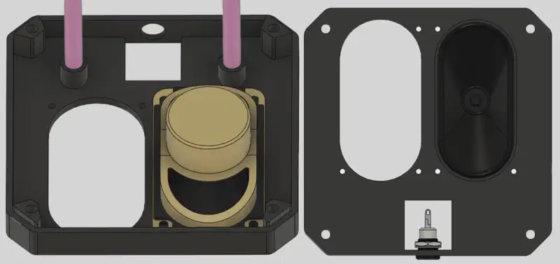
The base of the Ghost consists of three main parts:
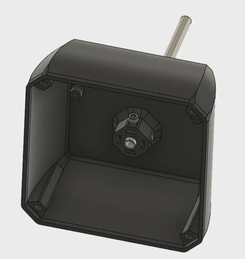
- Main Body: The top piece serves multiple functions. It is where the PCB is mounted and includes cutouts for the display and buttons. Additionally, it has a mount for the motor and a cutout for fitting the central linear bearing.

- Speaker Mount: The second piece, located directly below the main body has two cutouts that serve as mounting points for the speakers. It also includes a cutout for a DC input and has two mounting points for the linear rails.
Fixing Audio Quality Issues
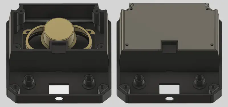
Unfortunately with this design, when playing voice lines the speakers sounded muffled so I first modified the design to fully seal the speaker inside of the base. This improved the sound quality but there were clearly still issues.
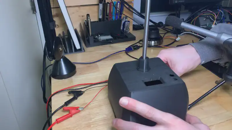
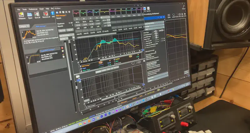
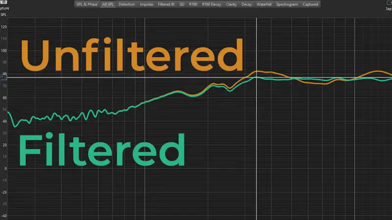
I first had to record the speaker playback at all frequencies from 100hz to 20000hz. This revealed the points where the speaker was either too loud or too quiet causing the audio quality issues. To fix this, in the software I was using I created filters that either boosted or cut at specific frequencies. I then applied these filters to the audio on the SD card and with that the voice lines sounded great.
- Cover Plate: The final piece is a cover plate that protects the speakers, provides a flat surface for the base to sit on, and covers the four exposed screws that hold the previous two sections together.

(The furthest right image shows a cross-section of the base with the cover plate on the bottom.)
3D Printing
FDM Printing
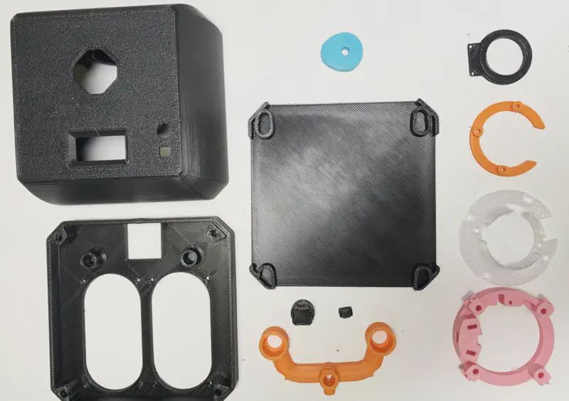
All parts in the base and any internal parts in the main ghost were printed using an FDM printer. These parts required no post-processing and were ready to use right out of the printer.
SLA Printing
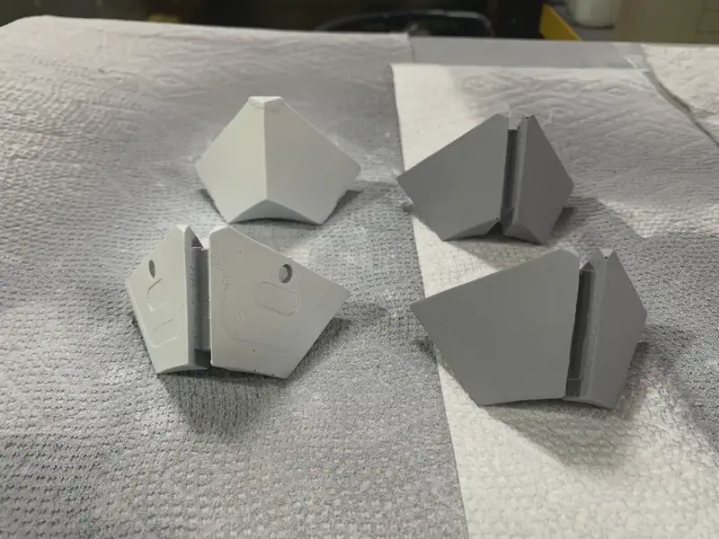
For the visible pieces on the ghost, I used resin printing. After some post-processing, these became the “master parts” for creating molds for the final parts.
Post-Processing Resin Prints
Preparing the resin prints for molding involved several steps:
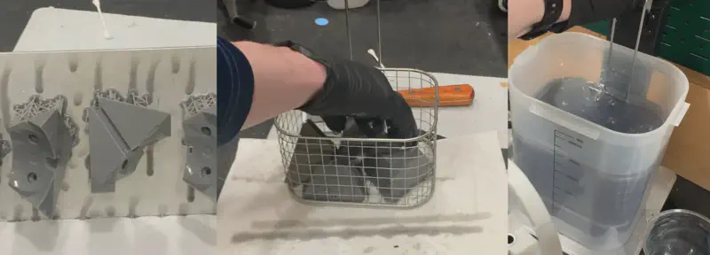
Initial Cleaning:
- I washed the freshly printed part in isopropyl alcohol for 2 minutes.
- Then, I rinsed it with soapy water for another 2 minutes.

Curing:
- I cured the part in UV light while submerged in clean water for 30 minutes. This prepared the part for handling.

Sanding:
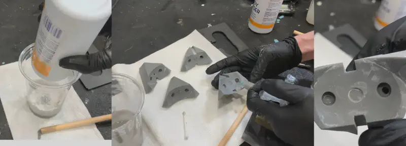
- I sanded off all support marks with 200 - 400 grit sandpaper to remove any major imperfections.

Filling Imperfections:
- For deep divots or gashes, I filled the spot with a mixture of the original resin and baby powder. This thickened the mixture, allowing it to stay in place and preventing it from running down the side of the part.
- I used this mixture to fill in the holes of any hollow resin parts, which were designed to let excess resin drain during printing. These holes needed to be filled before casting the parts in silicone to prevent them from filling with silicone and ruining the mold.

- Smoothing:
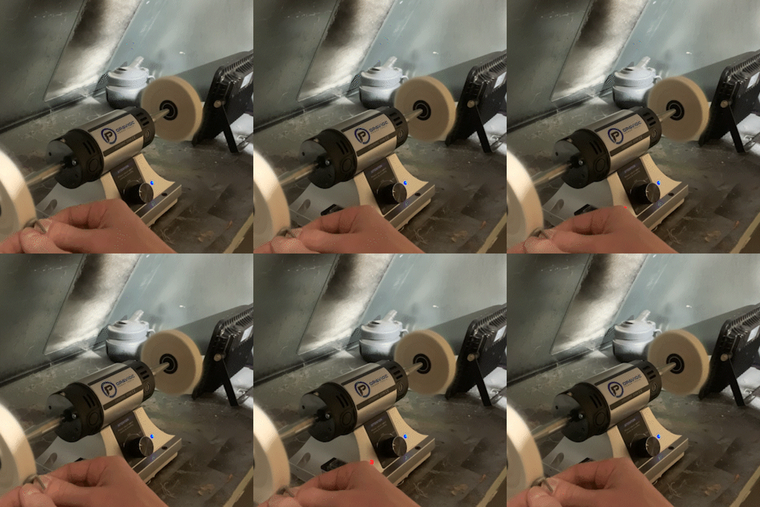
- For parts that needed to be glass smooth, I sanded down to 800 grit and then polished with finer and finer grits.
- After polishing, I used an ultrasonic cleaner to remove the caked-on polishing compound.
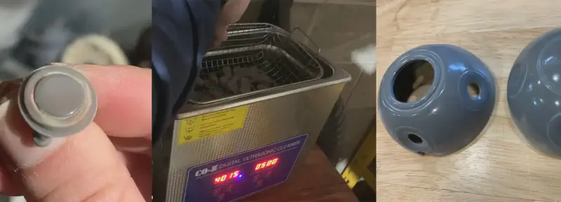
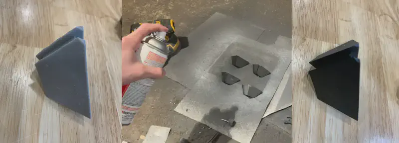
Painting and Sealing:
- For all other parts, I found that 400 grit was a good place to stop. I painted these parts and then sealed them with a clear matte spray paint, giving a slightly textured surface. This also helped to hide any inevitable small imperfections.

Final Curing:
- Before making molds with these parts, I baked them overnight at 150°F to finish the resin curing process and fully dry any paint.
- I washed them with soap and water one last time to remove any residual contaminants.
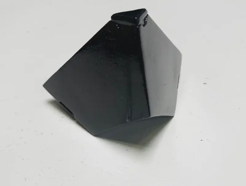
Mold Making
The post-processing steps prior were exhaustive because of the extreme sensitivity of platinum cure silicone to even the smallest amount of uncured resin or paint. Any contamination could cause the silicone to become cure inhibited, meaning it would remain permanently liquid and ruin the mold.
Challenges in Mold Making
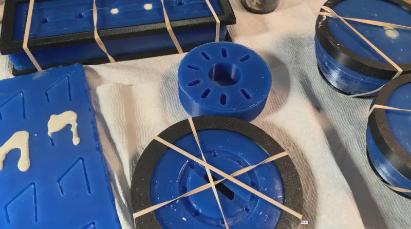
Most of the parts were quite difficult to mold, with many requiring two-part molds. Some parts had through holes that needed to be temporarily filled with extra pieces while molding the first half, then removed for the second half.

Designing Mold Boxes and Keying Structures
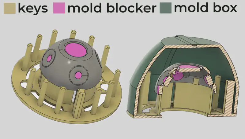
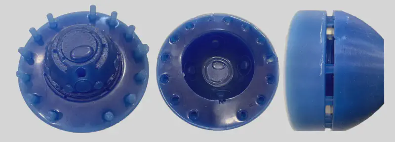
The easiest way I found to mold the most complicated parts, specifically the front half of the ghost shell with all its cutouts and thin structure, was by designing mold boxes and keying structures specific to each part.
The yellow structure below might look complicated, but its only purpose is to hold the shell in the middle of the mold box and create keys in the silicone so the two parts of the finished mold will lock together.
Mold Making Process
This image shows how the mold would look half-finished, with the blue being the finished first half of the mold and the yellow being vents and a fill port.
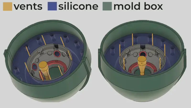
All of the other molds were made in fundamentally the same way, but with most of them requiring one or two fewer steps due to their simpler geometry.
Polyurethane Parts
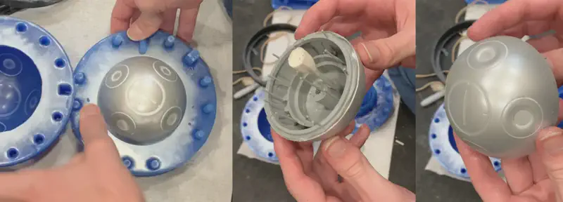
With all the molds finished, I could start casting some parts. I chose polyurethane for this due to its fast cure time of less than 10 minutes, good strength, and ability to deform instead of cracking. These properties make it ideal for these types of parts.
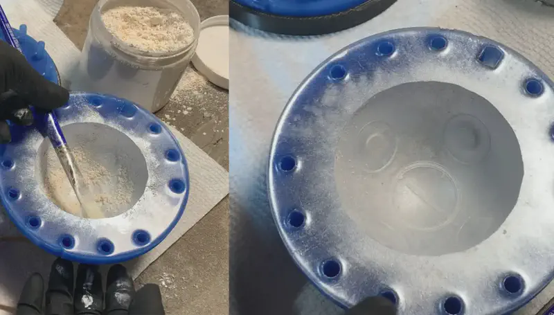
To replicate the metallic appearance of the in game Ghost, I added silver mica powder to one half of the mold for each side of the shell. By adjusting the darkness of the polyurethane mix, I could achieve a range of appearances, from a silver look to a more steel-like appearance.
Custom Tools
Casting the shells wasn’t as simple as pouring the polyurethane and letting it cure. I needed to find a way to cast them as hollow structures. After researching various methods, I discovered that rotocasting was the best approach. This technique involves rotating the mold in all directions while the polyurethane is setting, resulting in a hollow shell.
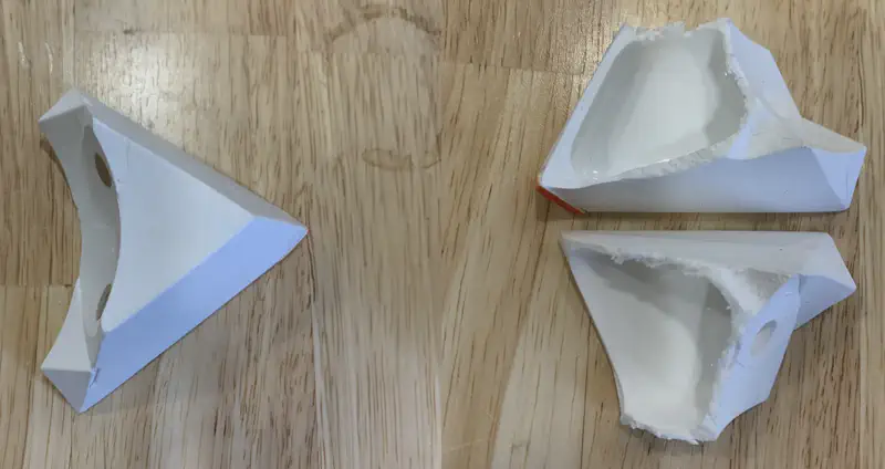
Building the Rotocaster
To achieve the necessary motion for rotocasting, I needed a specialized machine. While commercially available rotocasters exist, they are quite expensive. So I decided to design and build my own rotocaster.
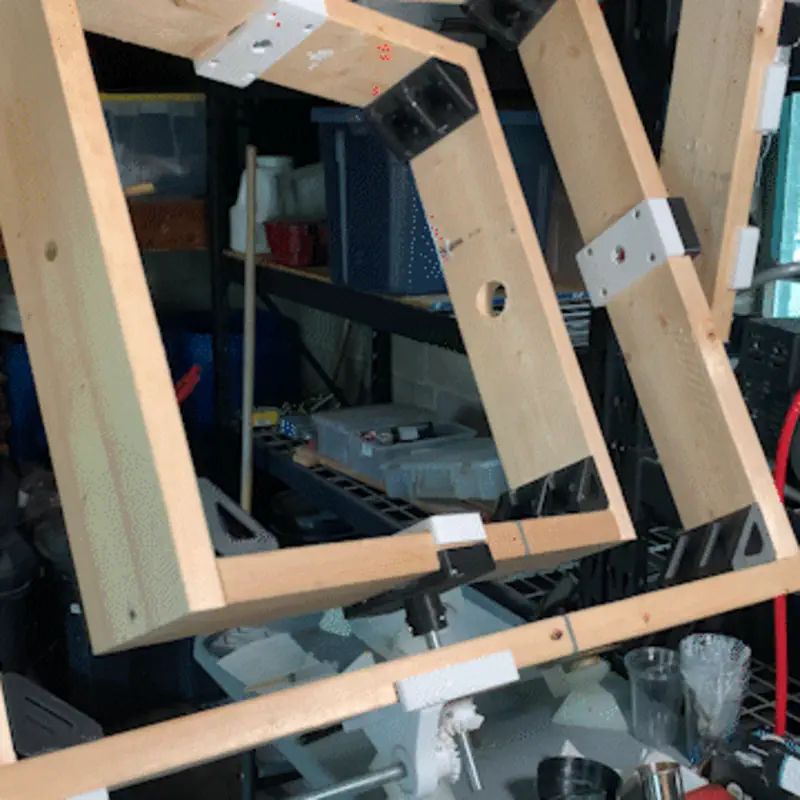
Rotocaster Construction
The basic construction consists of:
- Outer Half Square: Fixed and serving as an anchor point.
- Large Inner Square: Receives direct rotational input from a motor, causing the mold to rotate around its primary axis.
- Smaller Inner Square: Rotates around a secondary axis, receiving input from the large inner square through a series of gears and chains.
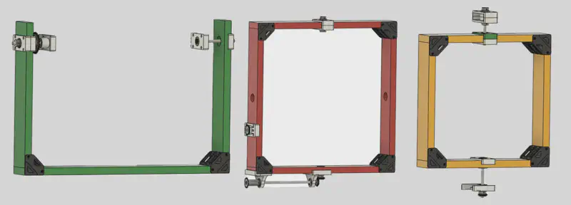
The components are connected using:
- 1/2 inch threaded rod
- 50+ mm diameter bearings
- 3D printed parts to connect everything and enable smooth motion transfer

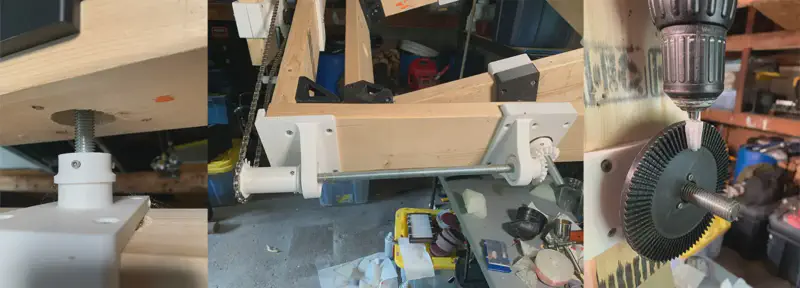
Painting
Outer Shell Painting
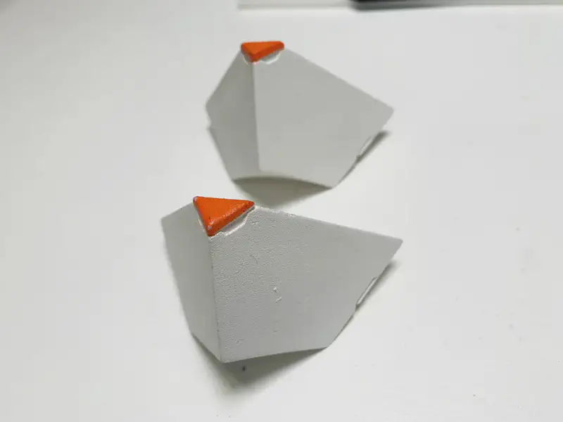
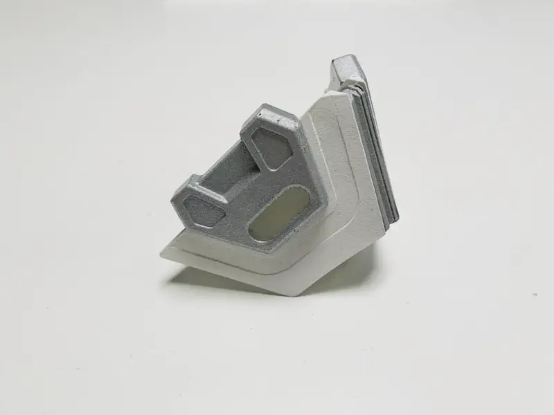
The only parts that need to be painted are the outer shell pieces. So far, I have painted the standard white shell and added orange accents. For the white base coat, I used a standard spray paint can, while with the orange accents I used an airbrush for more precision.
Early Paint Defects
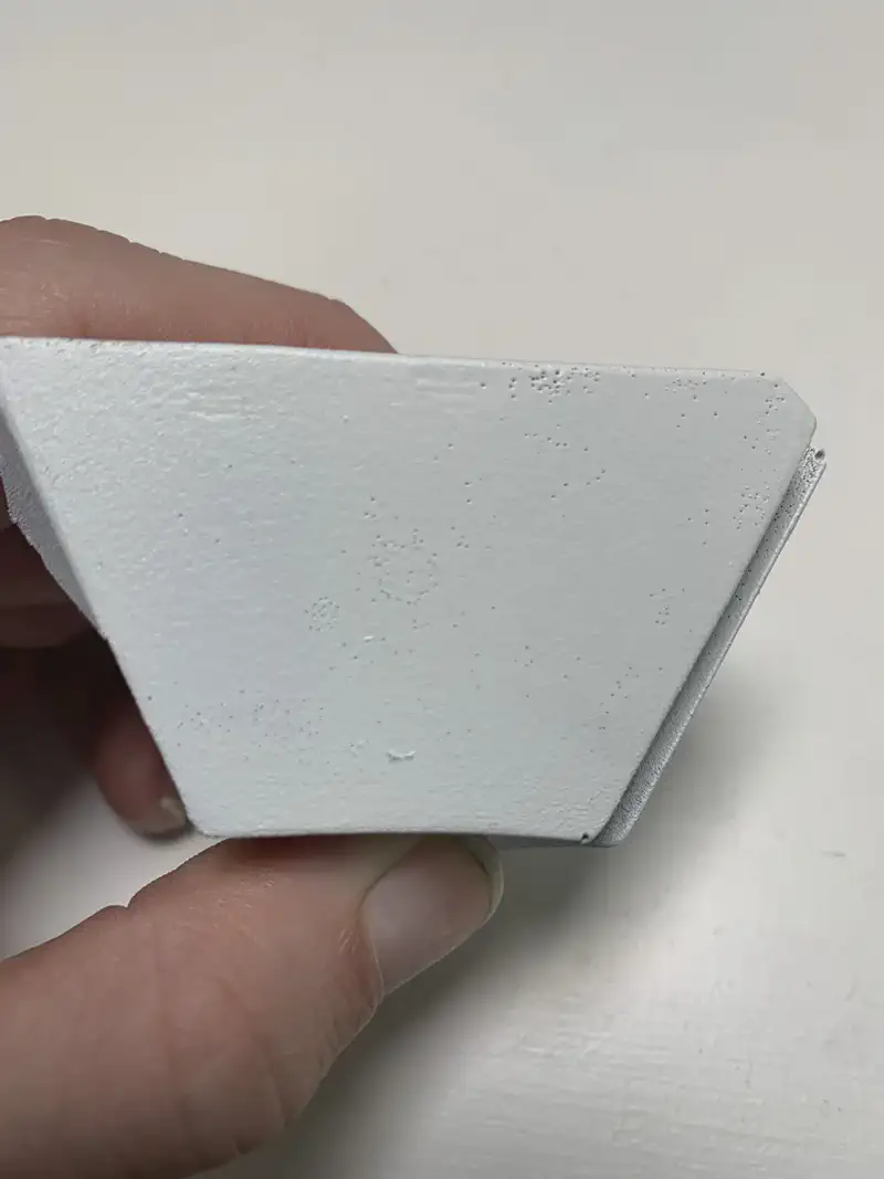
During the rotocasting process, I encountered an issue where tiny micro bubbles would form on the surface of the polyurethane. These bubbles caused defects in the paint coat. To resolve this, I refinished the master shells with a smoother clear coat instead of the matte finish I initially used. This adjustment significantly reduced the number of bubbles and imperfections in finished parts.
Accent Pieces
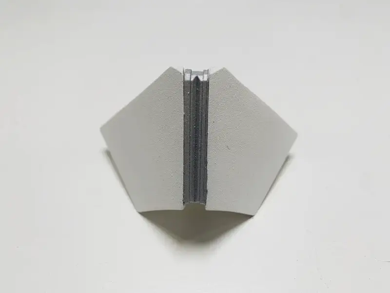
For the accent pieces, I used a silver metallic spray paint.
Customization Potential
One of the great features of the Ghost is its ease of customization. The possibilities for paint designs are endless. Eventually I plan on making a bunch more designs but for now I have only made the standard white and orange version.
User Controls
Ghost Menu Diagram
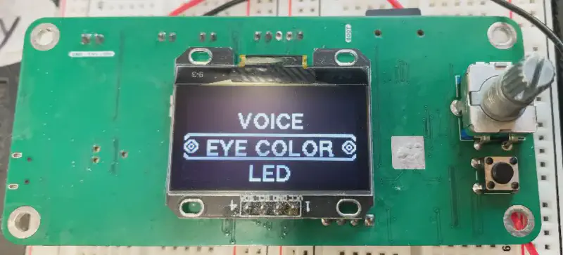


Speed: Adjusting the speed setting in the LED menu will increase the speed of the set animation, if one is selected.
Delay: Increasing the delay setting will cause the Ghost to wait longer before performing actions such as the hover effect, eye motion, shell spin, voice lines, or LED animations.
Led ON/OFF: Allows for turning each individual led on and off.
Final Assembly
All the hardware for the hover effect will be in its own section because of how finiky it still is. And the fact that I plan to only make the stationary ghost for now.
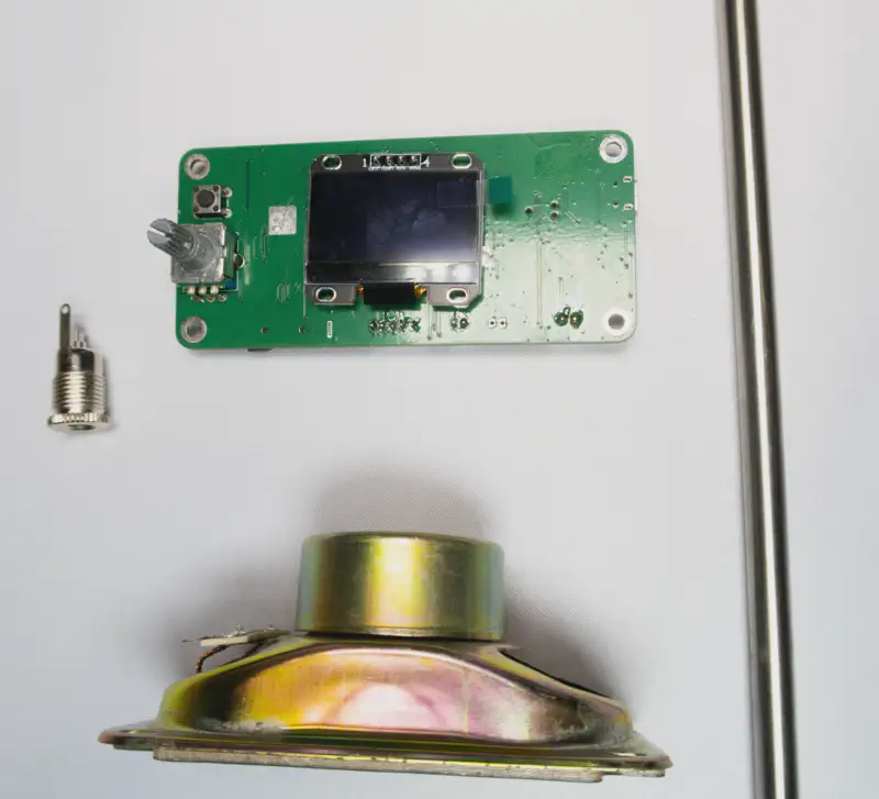
Base Parts
- Main PCB
- DC Barrel Jack Input
- Speaker
- 8mm Diameter Stand Rod
Ghost Parts
- Main PCB
- Hall PCB
- 36mm NEMA 14 Stepper Motor
- Power Cable
- Data Cable
- LEDs
- Lens
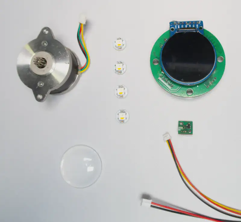
Base Hardware
Ghost Hardware
Ghost Magnets
3D Printed Parts
Base
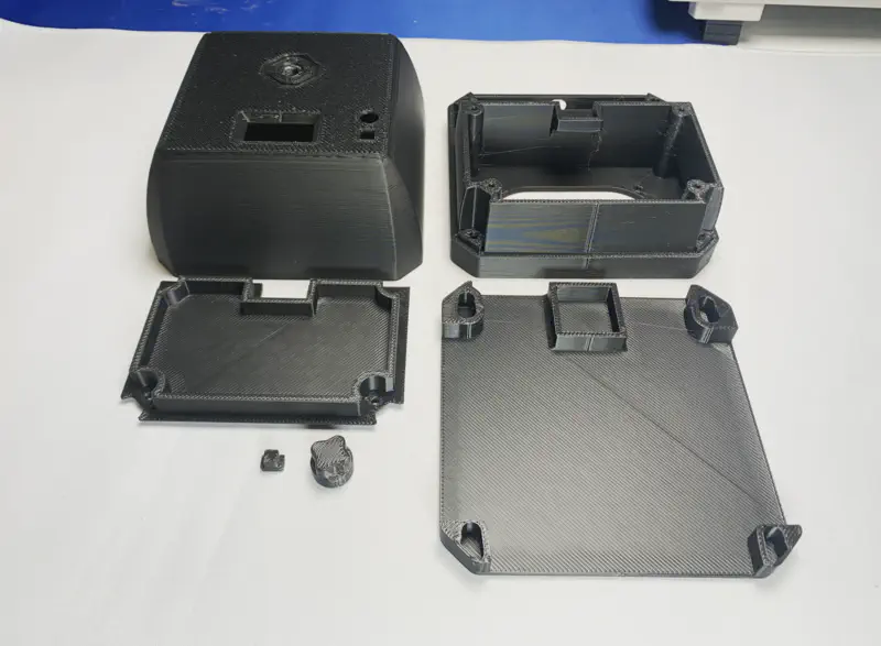
Shell

Molded Parts

Hover Effect Parts
Hardware
3D Printed Parts
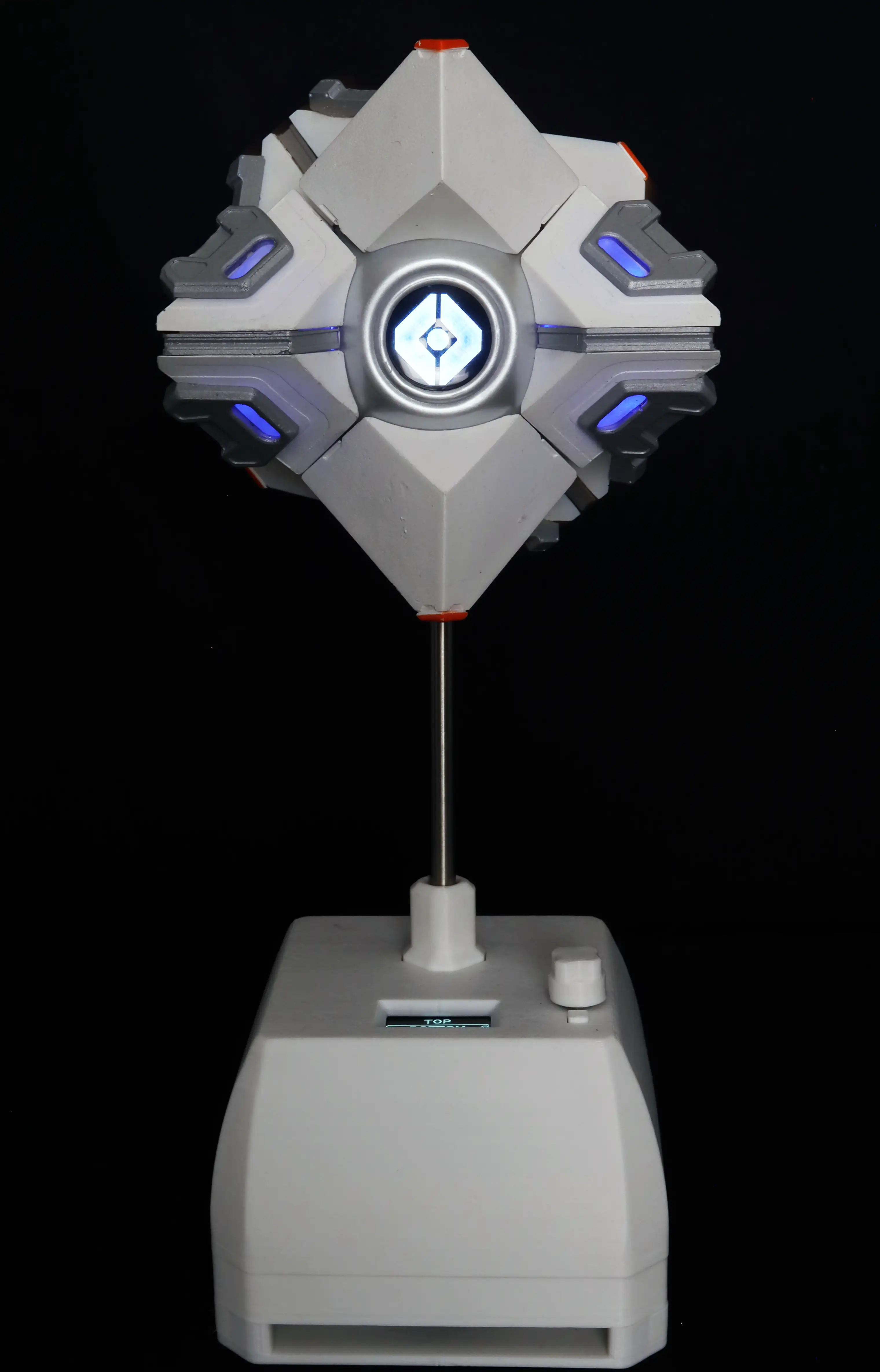
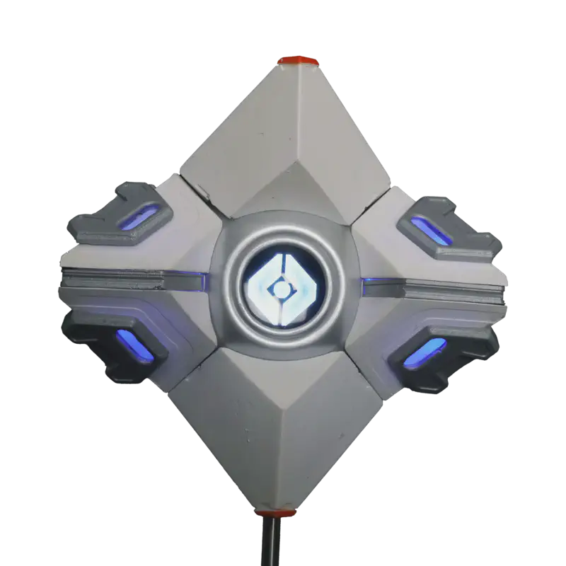
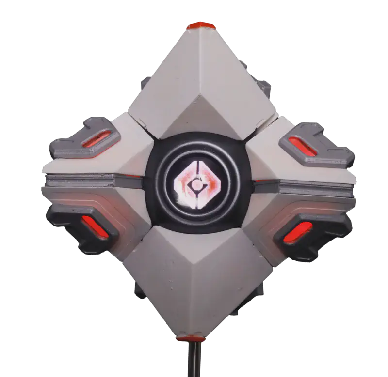
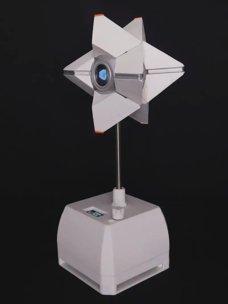
Finished Ghost

BOM
To purchase the ghost check out the Kickstarter page here.S
And after the Kickstarter is over I will be adding to the shop all the parts needed to build your own ghost.
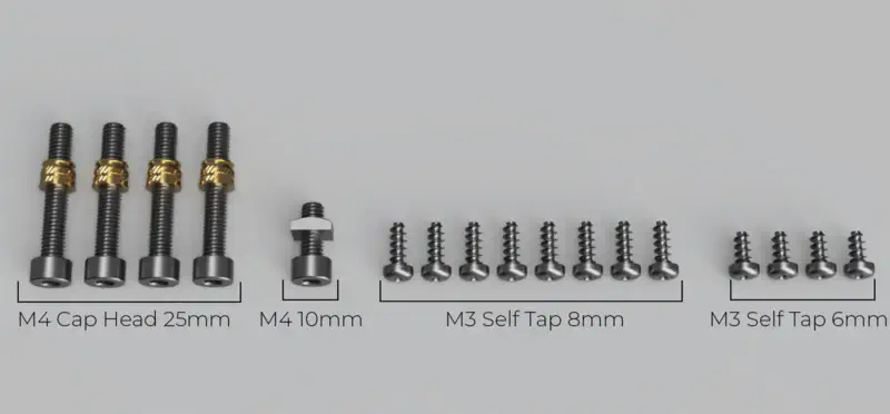
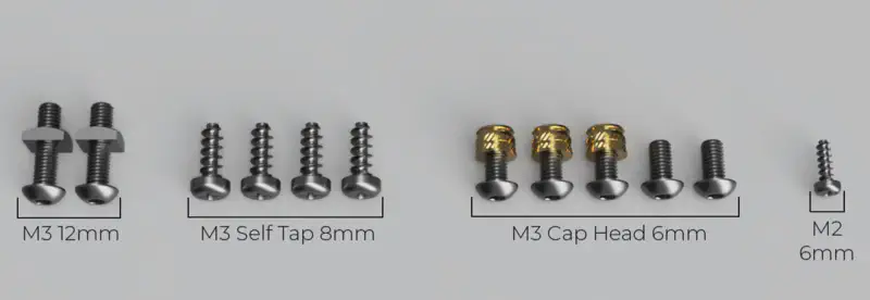
Fasteners
Ongoing Improvements
I am currently working on several improvements to enhance the Ghost project:
Code Maintainability:
- Refactoring the existing code to improve its structure and readability.
COMPLETED - Speaker and Sound Quality:
- Enhancing the speaker system for better sound quality.
- Integrating a dedicated speaker box to improve audio output.
- Verifying the sound quality using a calibrated microphone and audio analysis software.
Base Design:
- Designing a smaller base that omits the speaker and motion capabilities for a more compact and streamlined version of the Base.
Manual:
- Creating a manual for the Ghost, including assembly instructions and troubleshooting tips
